
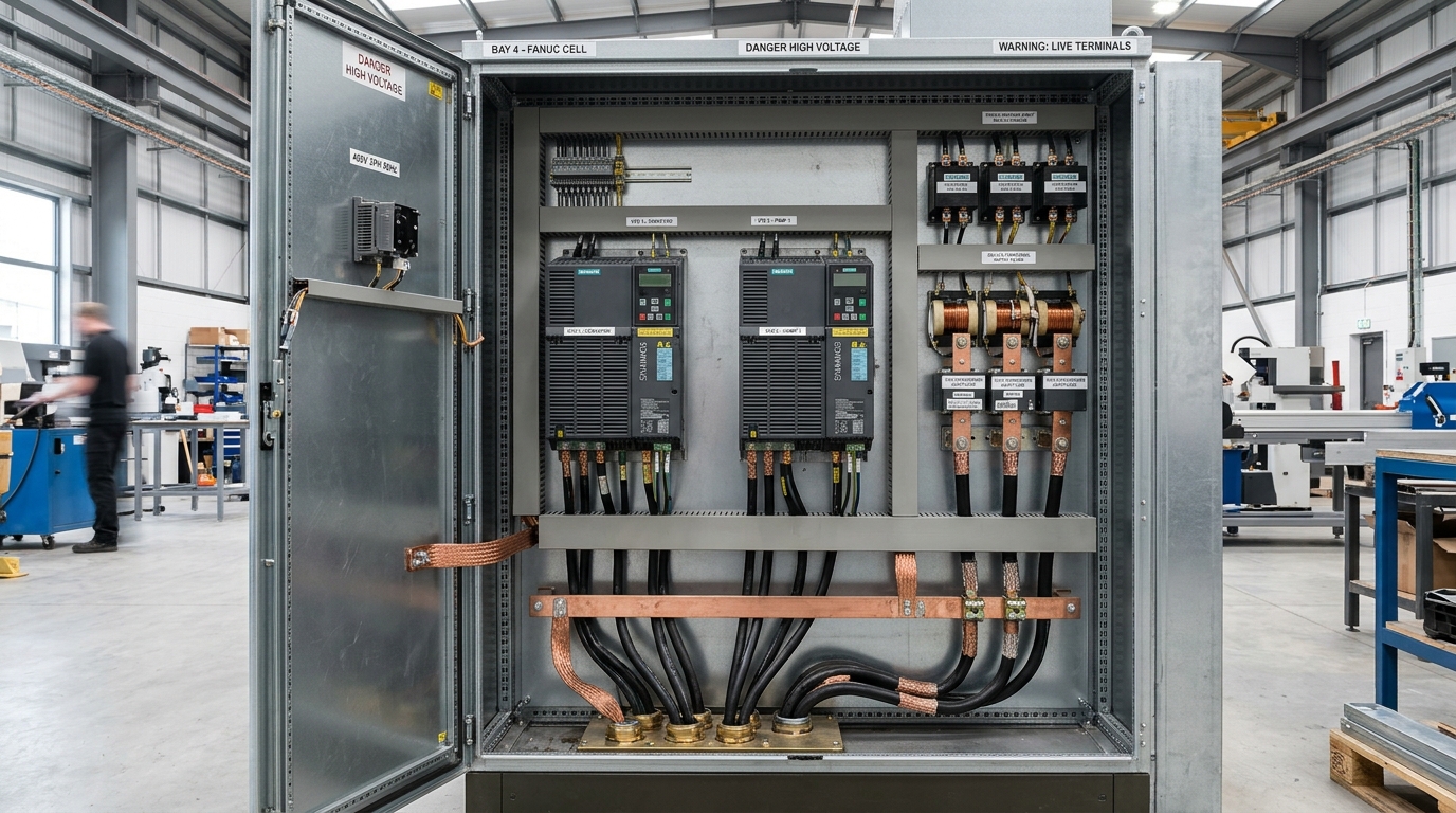
The Physics of VFD Electrical Noise: Why Pulse-Width Modulation Radiates
To eliminate erratic automation faults, electrical design engineers must understand the physical mechanism of high-frequency noise generation inside a Variable Frequency Drive. An inverter takes three-phase 400V 50 Hz utility AC, rectifies it into smooth 560V DC via an internal capacitor bank, and chops that DC voltage into high-speed square-wave pulses using IGBT power semiconductor switches to recreate variable-frequency AC.
Modern IGBTs switch on and off in mere fractions of a microsecond. The rate of voltage change across time, known mathematically as du/dt, frequently exceeds 5,000 to 10,000 Volts per microsecond (V/μs):
Where:
- i_leak = High-frequency capacitive leakage current flowing into ground (Amperes).
- C_parasitic = Stray capacitance between motor cable cores, cable shielding, motor windings, and earth frame (typically 150 to 300 pF per metre).
- du / dt = Voltage rise rate of the inverter IGBT switching transition (V/s).
Because du/dt is astronomical, substantial high-frequency common-mode current pulses (often 10A to 30A peak) surge through stray capacitances at frequencies extending from 150 kHz to over 30 MHz. This noise must return to the inverter DC bus. If the control panel lacks a low-impedance high-frequency return path, this current circulates through external plant building steel, pipework, and safety earth loops, blinding analog sensors and resetting microprocessors.
The Pigtail Fallacy: High-Frequency Skin Effect and Inductance Physics
In standard 50 Hz power wiring under BS 7671, stripping the copper braid of an armored cable and twisting it into a single wire (known in the trade as a "pigtail") to land on a green-and-yellow earth terminal block is common practice.
Why Pigtail Earths Are Fatal to Industrial Automation
While a 10cm pigtail wire exhibits negligible DC resistance (less than 0.002 Ohms at 50 Hz), straight wire possesses an intrinsic self-inductance of approximately 1.0 nanohenry per millimetre (1.0 nH/mm). Therefore, a 100 mm pigtail presents 100 nH of parasitic inductance:
At 50 Hz, this impedance is 0.00003 Ohms (harmless). But at 20 MHz (the dominant radiated harmonic of an IGBT edge), the impedance of that identical 10cm pigtail climbs to:
Z_L = 2 × 3.1416 × 20,000,000 × 100 × 10^-9 ≈ 12.57 Ohms!
A 12.5 Ohm obstacle at 20 MHz effectively represents an open circuit to radio-frequency currents. Instead of returning safely through the shield to the drive chassis, high-frequency currents are forced to radiate outward into the air, turning the motor cable into a high-power broadcast antenna that couples directly into adjacent PLC communication cards.
The Solution: True 360-Degree Continuous Shield Grounding
To maintain shield effectiveness, the braided screen of motor and signal cables must be clamped circumferentially around its entire 360-degree perimeter at the exact point of cabinet entry:
Brass EMC Cable Glands
Heavy-duty nickel-plated brass EMC glands feature an integrated conical spring or circumferential contact iris that clamps directly onto the exposed cable braid as the gland cap is tightened. This bonds the shield directly to the metallic enclosure base plate with less than 0.02 Ohms transfer impedance.
EMC Shield Saddle Clamps
Spring-loaded stainless steel saddle clamps mounted on an unpainted copper or galvanized busbar strip directly beneath trunking entries provide continuous mechanical pressure against stripped cable braid. This accommodates thermal expansion while maintaining large surface-area contact.
High-Frequency Surface Bonding: The Unpainted Galvanized Backplate Mandate
A standard industrial control panel enclosure is painted or powder-coated in RAL 7035 light grey. While aesthetically clean and corrosion-resistant, industrial powder coating is an excellent electrical insulator.
At high frequencies, electrical currents do not travel through the core of conductors; due to the Skin Effect, RF currents flow entirely along the outer surface skin:
Where:
- δ (delta) = Skin depth in metres (the depth at which current density drops to 37%).
- ρ (rho) = Resistivity of copper (1.68 × 10^-8 Ω·m).
- μ (mu) = Magnetic permeability of the conductor.
- f = Frequency of the noise component (Hz).
At 50 Hz, skin depth in copper is 9.3 mm. But at 10 MHz, skin depth drops to a paper-thin 0.02 mm (20 microns)! High-frequency currents require maximum surface area, not cross-sectional thickness.
Why MASK Controls Mandates Galvanized Backplates
If VFD metal chassis frames, RFI filters, and cable grounding brackets are bolted onto painted backplates using standard serrated washers, contact occurs only at microscopic paint scrape points. The resulting contact impedance is high, destroying RF equipotential bonding.
For every high-performance automation panel built at MASK Controls, our workshop standardises on unpainted, passivated galvanized or zinc-plated steel backplates. The entire metallic surface becomes an unbroken, zero-impedance RF ground plane. Furthermore, panel doors, side walls, and chassis frameworks are linked using flat braided copper earth straps (which exhibit 80% lower high-frequency impedance than round copper cables).
Line Reactors, RFI Filters, and Output du/dt Choke Sizing
Passive magnetic and capacitive filtering components are the physical heavy lifters of VFD electromagnetic compliance under BS EN 61800-3. Selecting the correct combination depends on supply impedance and cable run lengths:
| Filter / Reactor Type | Physical Location | Primary Engineering Function | When to Deploy |
|---|---|---|---|
| Input Line Choke (Mains Reactor) | Between incoming breaker and VFD input terminals. | Adds 2% to 4% impedance to smooth diode current peaks, reduces THD, and absorbs grid voltage spikes. | Mandatory on low-impedance utility supplies or when transformer kVA > 10x VFD rating. |
| Input RFI / EMC Filter | Adjacent to VFD input, mounted flat on galvanized backplate. | Suppresses conducted radio-frequency emissions (150 kHz to 30 MHz) back into factory mains. | Required to meet BS EN 61800-3 Category C1 or C2 emission limits. |
| Output du/dt Filter | Between VFD output inverter and motor cable. | Reduces voltage rise time (du/dt) from 5,000 V/μs down to < 500 V/μs, capping reflection spikes. | Essential for motor cable runs between 30m and 100m, or older non-inverter motors. |
| Sinusoidal (Sine-Wave) Filter | Directly at VFD inverter output terminals. | Converts raw PWM square wave into smooth sinusoidal phase-to-phase AC voltage. | Long cable runs (> 100m), submersible pumps, or unshielded retrofitted cables. |
The Long-Cable Reflected Wave Phenomenon (Transmission Line Effects)
When a high-speed PWM pulse travels along a motor cable, the cable acts as a distributed transmission line. The surge impedance of typical industrial motor cable is approximately 80 to 120 Ohms, whereas the surge impedance of an electric motor winding is several thousand Ohms.
When the voltage pulse reaches the motor terminals, this dramatic impedance mismatch causes the pulse to reflect back along the cable, in phase with incoming pulses. Under worst-case cable lengths (critical length L_crit approximately 10m to 25m), the peak voltage at the motor terminals doubles:
These repeated 1,400V microsecond spikes tear through standard phase insulation enamel on motor windings, causing premature inter-turn short circuits and sparking high-frequency Electrostatic Discharge Machining (EDM) currents through motor ball bearings. Installing an output du/dt filter caps peak terminal voltage below 1,000V, extending motor service life from months to decades.
Internal Cabinet Zoning Architecture: The Four-Zone Partition Rule
No amount of filtering can overcome poor internal wiring geometry. In an automated control panel where heavy 400V drives share cabinet space with delicate 24V DC microprocessors, our systems design team enforces rigorous Four-Zone Spatial Segregation:
Supply Entry & Breakers
Houses incoming three-phase terminals, mains isolator, primary fusing, and input line reactors. Placed at the top or bottom corner, immediately isolated from all digital control circuits.
Inverter Drives & Braking Resistors
Houses VFD power modules, DC link chokes, and dynamic braking choppers. Motor cables exit immediately through dedicated bottom gland plates without traversing other zones.
PLC CPU & 24V DC Digital I/O
Houses 24V DC switched-mode power supplies, PLC racks, safety relays, and digital 24V discrete sensor terminals. Physically separated by at least 200 mm from Zone 2.
Industrial Ethernet, Fieldbus & 4-20mA
Houses PROFINET/EtherNet-IP managed switches, IO-Link masters, and 4-20mA instrumentation loops. Routed exclusively in grounded metallic wireways with twisted-pair foil shields.
The Orthogonal 90-Degree Cable Crossing Rule
Never route 400V inverter motor cables parallel to control or communication wiring in the same trunking. Parallel conductors create strong mutual inductance ($M$), transferring noise continuously along their length. If power cables and sensor wiring must intersect, they must cross strictly at a 90-degree right angle. Orthogonal crossing cancels mutual magnetic field coupling to zero.
UK Statutory Compliance: BS EN 61800-3 & UKCA EMC Declaration
For UK machinery manufacturers and factory operators, electromagnetic compliance is a criminal legal obligation enforced under the Electromagnetic Compatibility Regulations 2016 (SI 2016 No. 1091). Under British law, every machine placed on the UK market must satisfy essential protection requirements:
Emission Limits (BS EN 61800-3)
The control panel must not emit conducted or radiated electromagnetic disturbances that exceed defined thresholds, ensuring nearby radio communications, IT infrastructure, and plant equipment operate without degradation.
Immunity Standards (BS EN 61000-6-2)
The internal automation system must demonstrate verified immunity against electrostatic discharges (ESD), electrical fast transients/bursts (EFT), surges, and radiated radio-frequency fields without tripping or crashing.
Every bespoke automation system and MCC panel delivered by MASK Controls includes full EMC design verification documentation, wiring layout schematics in EPLAN, and signed UKCA / CE Declarations of Conformity supporting authorized machinery deployment.
Explore our full range of turnkey capabilities in bespoke control panel design, complex multi-vendor PLC programming, and on-site commissioning and testing services.
Frequently Asked Questions (VFD EMC Engineering)
Click any question below to explore technical answers regarding VFD noise suppression, grounding standards, and BS EN 61800-3 compliance.
Q1:Why does a 10cm twisted pigtail wire destroy cable shield effectiveness at radio frequencies?
Q2:What is the physical difference between an input line choke and an output du/dt filter?
Q3:Why must VFDs and RFI filters be mounted on unpainted galvanized backplates?
Q4:How does BS EN 61800-3 categorize VFD installations in commercial versus industrial facilities?
Q5:How can panel builders prevent 24V DC analog sensors from erratic readings near high-power drives?
Eliminate VFD Noise & Fieldbus Communication Failures with MASK Controls
Whether retrofitting multi-axis servo drives, designing high-power motor control centres with du/dt filtering, or solving persistent analog sensor drift on existing UK production lines, MASK Control Systems delivers turnkey, noise-immune EC&I engineering.
Need an Industrial EMC or VFD Noise Audit?
Speak directly with our senior drives and control systems engineers in Devon. We design, build, filter, and commission robust industrial control panels for UK manufacturers and OEM machine builders.