
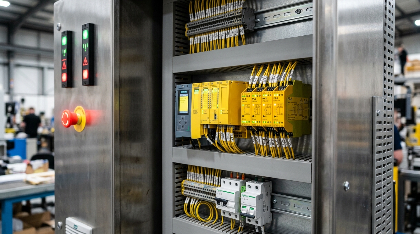
Foundational Standards: BS EN ISO 13849-1:2023 vs IEC 62061
In European and UK machinery directives, complying with the Supply of Machinery (Safety) Regulations 2008 and PUWER 1998 requires functional safety verification through harmonised standards. For electrical, electronic, and programmable safety-related systems (SRCFS), two primary standards govern industrial compliance: BS EN ISO 13849-1 (Performance Levels PL a through PL e) and BS EN IEC 62061 (Safety Integrity Levels SIL 1 through SIL 3).
Debunking the Primary Industry Myth: PL e Is Not Exclusive to PLCs
A common misconception among machinery buyers and plant maintenance teams is that a programmable Safety PLC is inherently "safer" or provides a "higher safety grade" than an electromechanical safety relay. Under ISO 13849-1, this premise is mathematically incorrect. Both technologies are certified to achieve the pinnacle ratings of Category 4 / PL e and SIL 3.
The logic solver (whether a Pilz PNOZ relay or a Siemens S7-1500F Safety CPU) represents only one constituent block of the safety loop: Input → Logic → Output. In real-world validation, the logic unit contributes less than 5% of the total dangerous failure probability. The weakest link is almost universally the physical actuators (weld-prone power contactors, pneumatic dump valves) or mechanical input switches subjected to physical wear.
The Four Mathematical Pillars of BS EN ISO 13849-1:2023
Under the revised BS EN ISO 13849-1:2023 edition, achieving a designated Performance Level requires validating four quantitative and qualitative metrics simultaneously:
Design Architecture (Category)
Defines structural fault tolerance. Cat B and Cat 1 are single-channel with zero fault redundancy. Cat 2 incorporates periodic testing. Cat 3 and Cat 4 demand redundant, dual-channel architectures where a single component fault will not lead to loss of the safety function. Cat 4 mandates continuous cross-monitoring that detects accumulation of undetected faults.
Mean Time to Dangerous Failure (MTTFd)
The statistical operating lifespan before a dangerous failure occurs. Grouped into three mathematical bands: Low (3 to 10 years), Medium (10 to 30 years), and High (30 to 100 years). Calculated per channel using manufacturers B10d data and operational cycle frequencies (nop).
Diagnostic Coverage (DCavg)
The percentage of dangerous failures detected by internal self-diagnostics. Categorized as None (DC < 60%), Low (60% to 90%), Medium (90% to 99%), and High (DC >= 99%). Cat 4 architectures strictly mandate DCavg of Medium or High.
Common Cause Failure (CCF)
Defense against environmental and systemic failures affecting both redundant channels simultaneously (e.g., thermal overload, electromagnetic noise, voltage spikes). Validated via a strict point-scoring matrix where a minimum of 65 points out of 100 is legally required.
Hardware Anatomy: Relays vs Failsafe Safety PLCs
Understanding how safety integrity is physically realized within the cabinet requires analyzing the distinct internal architectures of electromechanical safety relays and microchip-driven failsafe controllers.
Electromechanical Safety Relay
A safety relay uses force-guided contacts (mechanically linked according to BS EN 50205 Type A). If a normally-open (N/O) power contact welds shut due to an inrush short-circuit, the internal mechanical bar physically prevents the normally-closed (N/C) monitor contact from closing.
- External Device Monitoring (EDM): Prevents restart if external contactor auxiliary contacts fail to return to rest state.
- Cross-Fault Detection: Sends opposing test voltages (e.g., 24V on Channel A, 0V on Channel B) across dual E-stop channels to detect cable pinch shorts instantly.
- Deterministic Execution: Direct hardware logic with reaction times under 15ms. Zero firmware, zero software compiler, zero memory corruption vectors.
Failsafe Safety PLC (F-CPU)
A Safety PLC executes a 1oo2D (1-out-of-2 with Diagnostics) or 2oo3 multi-core redundant microprocessor architecture. Two independent processing cores execute identical safety logic simultaneously using diverse compilation or inverted memory mapping.
- Clock Cross-Comparison: Continuous hardware comparator checks register outputs between cores. A 1-bit discrepancy trips the system to safe state within 1 cycle.
- Dark & Light Test Pulses: Digital safety outputs emit sub-millisecond test pulses (dark tests) to confirm output transistors can switch off without dropping actuator power.
- Certified F-Libraries: TÜV-certified function blocks for emergency stop, light curtain muting, two-hand control, and interlocks locked against runtime manipulation.
The Safe Networking Revolution: The Black Channel Principle
In traditional relay cabinets, every safety input and contactor feedback loop requires dedicated, multi-core shielded copper wiring running back to central terminal strips. In modern modular production plants, this hardwired model breaks down. The industry solution is Safety over Fieldbus governed by IEC 61784-3.
How the Black Channel Principle Operates in Practice
The Black Channel concept treats the transmission medium (standard Ethernet switches, Cat6 cables, Wi-Fi bridges, slip rings, and standard operating system protocol stacks) as untrusted and potentially unreliable. Instead of certifying every network switch to SIL 3, the safety data packet carries its own mathematical armor:
Cyclic Redundancy Checks detect any corrupted or transposed bits caused by EMC interference.
Consecutive numbering detects dropped, repeated, or out-of-order telegram packets instantly.
Timestamp acknowledgment ensures packet age cannot exceed maximum allowable safe reaction time.
Unique Safety Network Numbers (SNN) verify data originates from and arrives at the designated device only.
Safe Motion (IEC 61800-5-2) vs Hardwired Power Contactors
Perhaps the single greatest engineering benefit of a Safety PLC architecture is direct integration with Safe Motion functions built into modern variable frequency drives (VFDs) and servo inverters:
| Safe Motion Function | Standard Definition | Traditional Hardwired Equivalent | Operational Advantage |
|---|---|---|---|
| Safe Torque Off (STO) | Disables gate drive pulses to IGBTs; motor cannot produce rotational torque. | Dual redundant 3-phase line contactors breaking motor power. | Zero mechanical wear, eliminates contactor coil heat, restarts instantly without re-energizing mains. |
| Safe Stop 1 (SS1) | Initiates a controlled deceleration ramp, then triggers STO once stopped. | Delayed off-relay triggering physical brakes or reverse-current injection. | Prevents high-inertia loads (centrifuges, saws) from coasting for minutes; reduces stopping distance by 80%. |
| Safely-Limited Speed (SLS) | Monitors motor shaft speed via safe encoder; trips if speed exceeds threshold. | Virtually impossible with electromechanical relays without complex external cam timers. | Enables safe manual jog/teach modes with guard doors open; dramatically slashes maintenance setup time. |
| Safe Direction (SDI) | Ensures motor can only rotate in one permitted direction (e.g., feed-out only). | Mechanical ratchets or complex interlocked forward/reverse contactor arrays. | Allows operators to clear jams while guaranteeing the drive cannot crush backward into the hazard zone. |
The Economic & Engineering Crossover Point (Real-World UK Cost Model)
To provide machinery OEMs and plant engineers with actionable data, MASK Control Systems audited real engineering hours, component BOM costs, and panel fabrication metrics across three standard machine scales: Small (2 safety functions), Medium (5 safety functions), and Large (12 safety functions).
| Machine Scope | Parameter | Hardwired Relay Approach | Failsafe Safety PLC Approach | Financial Verdict |
|---|---|---|---|---|
| Small System (2 Functions) 1x E-Stop, 1x Guard Interlock | Hardware BOM | £320 (2x PNOZ Relays + Bases) | £1,450 (Compact F-CPU + I/O) | Safety Relay Wins Relay is £1,180 cheaper total. Zero software license needed. |
| Panel Space & Wiring | 90mm DIN rail, 4.5 wiring hrs | 160mm DIN rail, 3.0 wiring hrs | ||
| Engineering & SISTEMA | 3.0 engineering hrs | 7.0 engineering hrs (Code + Config) | ||
| Medium System (5 Functions) 2x E-Stops, 2x Gates, 1x Light Curtain, 2 Safe Zones | Hardware BOM | £1,250 (5x Relays + Interlock modules) | £1,850 (F-CPU + 16/8 F-DI/F-DO slice) | Crossover Point: Tie / PLC Wins Higher PLC hardware cost offset by 11 fewer wiring hours and HMI text diagnostics. |
| Panel Space & Wiring | 380mm DIN rail, 18.0 wiring hrs | 190mm DIN rail, 7.0 wiring hrs | ||
| Engineering & SISTEMA | 8.0 engineering hrs | 9.5 engineering hrs | ||
| Large Cell (12 Functions) 6x E-Stops, 4x Safety Gates, 2x Area Scanners, STO to 6 Drives, 4 Zones | Hardware BOM | £3,900 (Complex relay array + timers) | £3,200 (F-CPU + Decentralised IP67 F-I/O) | Safety PLC Decisively Wins PLC saves £2,800+ total, frees 60% enclosure volume, and eliminates field junction boxes. |
| Panel Space & Wiring | 950mm DIN rail, 52.0 wiring hrs | 280mm DIN rail, 14.0 wiring hrs | ||
| Engineering & SISTEMA | 24.0 engineering hrs (complex logic tracing) | 16.0 engineering hrs (modular function blocks) |
The Hidden Maintenance Cost: Mean Time to Repair (MTTR)
When a safety channel trips on an automotive or packaging line, production stops instantly. On a hardwired relay panel, technicians must decipher blinking LED codes or manually trace series-wired N/C auxiliary contacts through wiring ducts with a multimeter. In plants with 10+ interlocks, locating an intermittent gate switch fault routinely takes 45 to 90 minutes of catastrophic downtime (£1,500 to £10,000+ per hour in lost throughput).
On a Safety PLC, the HMI screen instantly displays: "Safety Zone 3 Open: Guard Door 4 East Hinge Switch Discrepancy Fault (Channel A closed, Channel B open)". The technician walks straight to the exact physical hinge within 60 seconds, resetting the line immediately.
Step-by-Step SISTEMA Calculation & Validation Methodology
To achieve legally defensible compliance under BS EN ISO 13849-1, every safety function must be modeled in SISTEMA (Safety Integrity Software Tool for the Evaluation of Machine Applications), published by the Institute for Occupational Safety and Health of the German Social Accident Insurance (IFA).
1Subsystem 1: Input (Sensors & Initiators)
Model dual-channel electro-sensitive protective equipment (ESPE / Light Curtains) or mechanically actuated tongue interlocks. Obtain the manufacturer B10d (number of operating cycles until 10% of components fail dangerously). Calculate operational switching cycles (nop = operations/hour × hours/day × days/year). SISTEMA then computes MTTFd = B10d / (0.1 × nop).
2Subsystem 2: Logic (Safety Relay or Safety PLC)
Import verified VDMA 66413 XML component libraries directly from manufacturers (e.g., Pilz, Siemens, Rockwell, Phoenix Contact, Omron). Because certified F-CPUs and safety relays are complete, sealed functional units, manufacturers provide pre-calculated PFHd (Probability of Dangerous Failure per Hour) values (typically 1.2 × 10⁻⁹ / hour) and predefined PL e / Cat 4 certification blocks.
3Subsystem 3: Output (Actuators & Power Contactors)
Model dual redundant electromechanical contactors wired in series to isolate the motor mains, with auxiliary N/C contacts routed back into the logic feedback monitoring loop (EDM). Alternatively, model the direct Safe Torque Off (STO) input terminals of the inverter drive. STO inputs yield virtually zero electromechanical wear compared to contactors, yielding significantly higher MTTFd values.
The Actuator Bottleneck: Why a £5,000 Safety PLC Cannot Save Bad Output Design
Under ISO 13849-1, the final achievable Performance Level of a safety loop is capped by the lowest scoring subsystem. If an automation engineer installs a Cat 4 / PL e Safety PLC, but uses a single standard 400V contactor without mirror contacts or feedback monitoring on the motor output, the output subsystem collapses to Category 1, capping the entire machine safety loop at PL c, regardless of the PLC sophistication.
UK Statutory Compliance: PUWER 1998 & UKCA Technical File
For plant owners and manufacturing operations directors in the United Kingdom, ensuring machinery compliance with PUWER 1998 (Provision and Use of Work Equipment Regulations) is a criminal law duty enforced by the Health and Safety Executive (HSE).
PUWER Regulation 11: Dangerous Parts
Mandates effective measures to prevent access to dangerous parts of machinery or stop movement before a person enters the danger zone. Safety circuits must achieve the designated Performance Level Required (PLr) calculated in the initial hazard assessment.
PUWER Regulation 15: Control Systems
Explicitly states that failure of any control system or its software, or any power disruption, shall not expose persons to danger. Software password locking, checksum verification, and formal change-management logs are legally mandated.
Every newly built or modified control panel delivered by MASK Control Systems includes a legally binding Technical Construction File (TCF) containing verified SISTEMA calculation reports, EPLAN CAD schematics, functional test certificates, and signed UK Declarations of Conformity supporting authorized UKCA and CE marking.
Frequently Asked Questions (Functional Safety Engineering)
Click any question below to explore technical answers regarding ISO 13849-1 compliance, safety networking, and cabinet architecture.
Q1:Can a hardwired safety relay achieve Performance Level e (PL e) and SIL 3 under ISO 13849-1?
Q2:What is the exact financial and functional crossover point between safety relays and a Safety PLC?
Q3:How does the 'Black Channel' principle work in safety fieldbuses like PROFIsafe and CIP Safety?
Q4:What are the major changes introduced in BS EN ISO 13849-1:2023 compared to the 2015 standard?
Q5:How does Safe Torque Off (STO) eliminate traditional redundant motor contactors?
Q6:What documentation does UK PUWER 1998 require for modified safety circuits?
Eliminate Machinery Safety Compliance Risk with MASK Controls
Whether retrofitting aging safety relay stacks on existing UK plant machinery or architecting brand-new Category 4 / PL e failsafe control panels with CIP Safety or PROFIsafe, MASK Control Systems delivers turnkey, TÜV-certified functional safety engineering.
Need a Formal ISO 13849-1 or SISTEMA Safety Audit?
Speak directly with our Functional Safety engineers in Devon. We design, build, program, and validate turnkey control panels for UK manufacturers and OEM machine builders.