
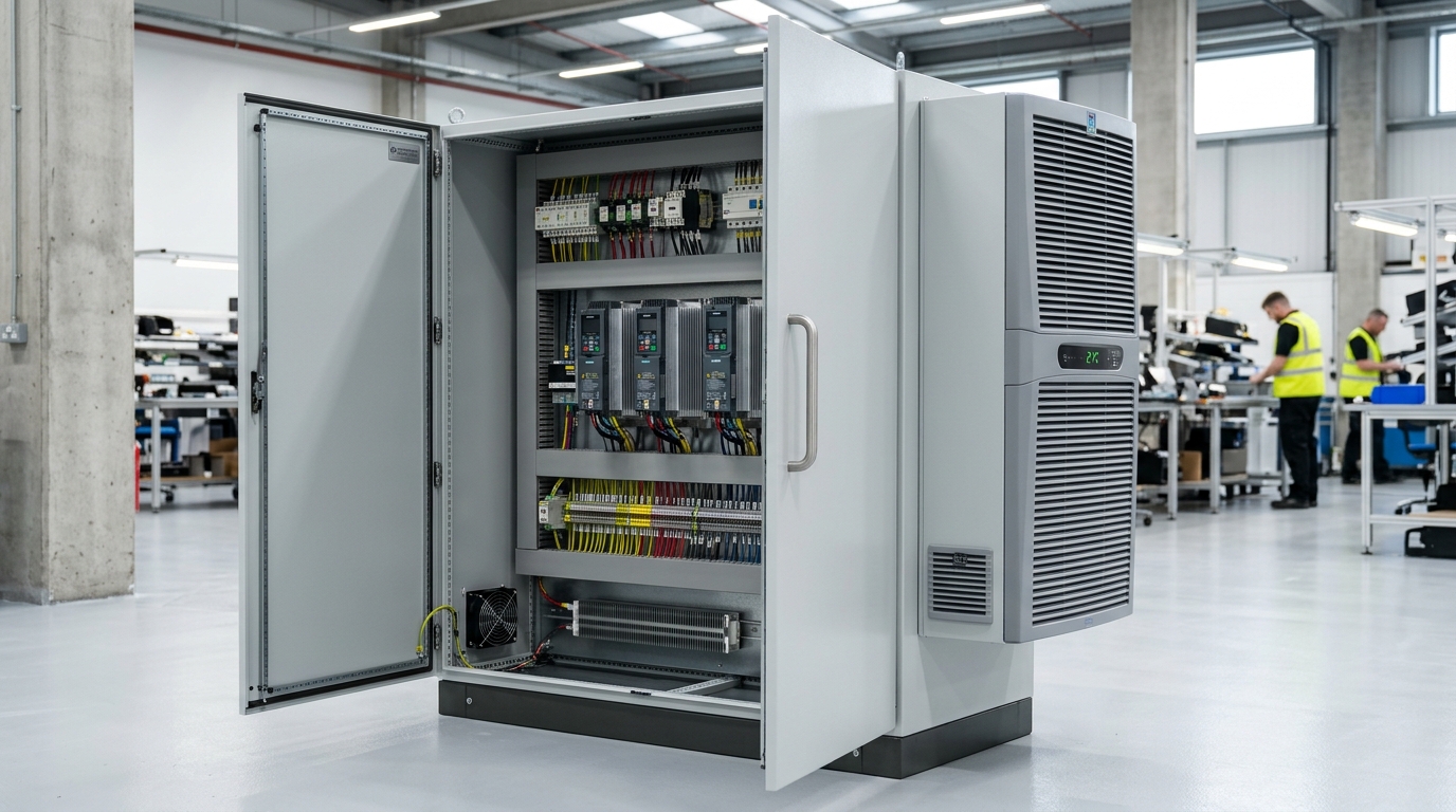
Component Heat Loss: Empirical Heat Dissipation Values
Every electrical and electronic device installed inside a control panel exhibits electrical resistance and switching inefficiency, converting a fraction of electrical throughput into parasitic thermal energy. Calculating the cumulative internal heat loss (Pv in Watts) requires aggregating the individual thermal contributions of all active hardware:
| Component Category | Typical Efficiency Rating | Empirical Heat Loss Rule of Thumb | Example Real-World Dissipation |
|---|---|---|---|
| Variable Frequency Drives (VFD) / Inverters | 97.0% to 97.5% | 2.5% to 3.0% of nominal motor kW rating | 15 kW drive → 410W to 450W heat loss |
| Servo Drives (Multi-Axis) | 96.0% to 97.0% | 3.0% to 4.0% of rated drive power | 7.5 kW servo drive → 260W heat loss |
| 24V DC Switch-Mode Power Supplies (SMPS) | 88.0% to 94.0% | 6.0% to 12.0% of output wattage | 24V 20A (480W) PSU → 45W to 55W heat loss |
| Programmable Logic Controllers (PLC Racks + I/O) | N/A (Direct consumption) | 100% of consumed electrical power converts to heat | Modular S7-1500 / GuardLogix rack → 35W to 65W |
| Line Reactors / Harmonic Chokes | 98.5% to 99.0% | 1.0% to 1.5% of connected motor rating | 15 kW input choke → 150W to 180W heat loss |
| Electromechanical Contactors & Relays | Coil holding power | 5W to 15W per active coil; 2W to 5W per main contact pole | Bank of 6 motor contactors → 60W to 90W heat loss |
| Control Transformers (400V to 230V / 110V) | 92.0% to 95.0% | 5.0% to 8.0% of VA capacity rating | 1,000 VA control transformer → 65W to 80W heat loss |
| Soft Starters | Internal bypass: 99.5% Non-bypass: 98.0% | With bypass: 5W to 15W Continuous thyristor conduction: 3W per Ampere | 45A continuous soft starter → 135W heat loss |
Worked Industrial Example: A Typical 3-Drive Packaging Panel
Consider a standard UK machinery control cabinet housing: 2x 7.5kW VFDs, 1x 15kW VFD, 1x 24V 20A power supply, 1x Safety PLC with 48 I/O channels, 1x 15kW line choke, 4x motor contactors, and 1x 500VA control transformer:
- Pv(VFDs) = (2 × 225W) + 420W = 870 Watts
- Pv(Choke) = 160 Watts
- Pv(Power Supply) = 50 Watts
- Pv(PLC System) = 45 Watts
- Pv(Contactors) = 40 Watts
- Pv(Transformer) = 35 Watts
- Total Internal Heat Dissipation (Pv) = 1,200 Watts
Enclosure Effective Surface Area (BS EN 61439-1)
Before determining whether active cooling equipment is required, electrical engineers must calculate how much thermal energy the enclosure can passively transfer through its steel skin to the ambient environment. Under BS EN 61439-1 and IEC TR 60890, the Effective Heat Dissipation Area (A in square metres) varies dramatically based on mounting orientation:
Free-Standing Enclosure (All Faces Exposed)
Maximum possible thermal radiation. Air circulates freely around front, rear, left, right, and top surfaces.
Wall-Mounted Enclosure (Rear Surface Blocked)
Rear surface has zero convective air circulation. Effective surface area drops by approximately 22%.
Suitcase / End-of-Row Enclosure (One Side Obstructed)
Common in multi-bay suites where bayed panels block thermal radiation through side panels.
Recessed / Alcove Enclosure (Rear and Both Sides Blocked)
Severely choked passive cooling. Effective radiation area drops by 45% or more; passive cooling is virtually impossible.
Heat Dissipation Capacity Formula (Passive Convection)
The passive thermal dissipation capacity of an enclosure (Qs in Watts) is calculated as:
Forced-Air Filter Fan Sizing: Mathematical CFM Formulas
When ambient factory air is reliably cooler than the internal cabinet design limit (Delta T >= 5°C) and airborne particulate levels permit an IP54 enclosure rating, forced ventilation filter fans provide the most cost-effective active thermal solution.
The Universal Airflow Calculation Formula
The volume of air (V) required to evacuate net thermal wattage depends on the specific heat capacity and density of air at standard sea level:
Where Qc is net cooling deficit in Watts, and ΔT is temperature difference (Ti - Tu) in Kelvin or °C.
Where ΔT is in degrees Fahrenheit (1 °C = 1.8 °F). 1 m³/h equals approximately 0.589 CFM.
Manufacturer catalog airflow ratings (free-blowing air) assume zero resistance. In real-world panels, the combination of an inlet filter mat, an exhaust louvre, internal wire ducting, and dust accumulation creates static backpressure. Always apply an operational de-rating multiplier of 1.25x to 1.35x to the calculated CFM to ensure adequate ventilation over the full maintenance filter cycle.
Airflow Direction Best Practice: Positive Pressure vs Extraction
A frequent panel builder mistake is installing the powered fan at the top of the cabinet in suction (extraction) mode. This creates negative internal pressure, drawing untreated factory dust and oily moisture through every unsealed door gasket, cable gland, and push-button cutout:
Recommended Standard: Positive Pressure Ventilation
Install the powered filter fan at the bottom third of the cabinet blowing inward. Install a passive louvre exhaust at the highest point diagonally opposite. This maintains positive internal pressure, forcing air outward through minor enclosure seams and utilizing natural thermal buoyancy (hot air naturally ascends to the upper exhaust).
Closed-Loop Air Conditioning Sizing (DIN 3168 / EN 14511)
When ambient plant air reaches 35 degrees Celsius or higher, ΔT drops to zero or becomes negative. Under these conditions, blowing 38 degree factory air into a cabinet will accelerate component overheating. A closed-loop enclosure air conditioning unit becomes physically mandatory:
| Operating Environment | External Ambient (Tu) | Enclosure Ingress Protection | Recommended Cooling Architecture |
|---|---|---|---|
| Clean Assembly / Warehouse | < 25°C | IP54 | Natural Convection or Filter Fan |
| Standard Machine Shop / Plastics | 25°C to 32°C | IP54 / IP55 | High-CFM Filter Fans or Air-to-Air Exchanger |
| Foundry, Bakery, Glass, High-Heat | 35°C to 50°C | IP55 / IP56 Sealed | Closed-Loop Industrial Air Conditioner (Side/Roof) |
| Food Washdown / Dairy / Beverage | 15°C to 30°C (High humidity) | IP66 / IP69K 316L Stainless | Air-to-Water Exchanger or Hygienic Sloped AC |
The Condensation Trap: Psychrometric Charts & Dew Point
In the UK climate, condensation causes more catastrophic electronic equipment failures than pure overheating. When moisture condenses on circuit boards, 24V DC logic tracks experience galvanic migration, producing intermittent bus faults and short circuits across terminal arrays.
How the Dew Point Destroys Electronics
Warm air can hold significantly more gaseous water vapour than cold air. If a control panel operates at 35 degrees Celsius with 70% relative humidity, its internal dew point is approximately 28.5 degrees Celsius. If an oversized air conditioner blasts cold air directly onto internal components, or if the factory cooling system drops cabinet wall temperature below 28.5 degrees Celsius during a night shift, air instantly reaches saturation (100% RH) and liquid water condenses directly onto copper traces.
The AC Temperature Setpoint Rule
Never set enclosure air conditioner thermostats below 32 to 35 degrees Celsius. Setting an AC unit to 20 or 22 degrees Celsius creates an extreme temperature differential across cabinet walls, causing aggressive condensation on external and internal steel surfaces while needlessly consuming electrical power.
Anti-Condensation Strip Heaters
Install PTC convection strip heaters at the lowest point of the enclosure, controlled by an electronic hygrostat set to 60-65% relative humidity. During winter shutdowns, the heater activates, keeping internal air temperature slightly above the ambient dew point to guarantee condensation cannot precipitate.
Operating Cost Comparison: Filter Fans vs AC vs Vortex Coolers
Selecting enclosure cooling requires evaluating total lifecycle operational cost, combining upfront procurement expenditure with annual electrical utility draw:
| Cooling Technology | Initial Capital Cost (BOM) | Electrical Power Consumption | Estimated UK Annual Running Cost | Maintenance Requirements |
|---|---|---|---|---|
| Forced-Air Filter Fans | £180 to £350 | 40W to 120W (AC/EC motor) | £60 to £160 / year | Quarterly filter mat cleaning or replacement |
| Closed-Loop Enclosure Air Conditioner | £1,200 to £2,800 | 450W to 950W (cycling compressor) | £450 to £950 / year | Annual condenser coil vacuuming; condensate drain check |
| Pneumatic Vortex Cooler | £450 to £750 | Consumes 25 to 35 CFM compressed air (~7.5 to 9.5 kW compressor load) | £2,400 to £3,600 / year | Zero moving parts; requires 5-micron pre-filtered dry air |
Frequently Asked Questions (Control Panel Thermal Management)
Click any question below to explore technical answers regarding enclosure thermal sizing, cooling equipment selection, and BS EN 61439-1 calculations.
Q1:What is the maximum internal operating temperature permitted inside an industrial control panel?
Q2:How do you calculate the required airflow (CFM or m3/h) for enclosure filter fans?
Q3:When must an enclosure air conditioner be specified instead of forced-air filter fans?
Q4:Why do industrial control panels require anti-condensation heaters even in hot factories?
Q5:How does enclosure mounting style affect effective heat dissipation surface area under BS EN 61439-1?
Q6:Are compressed air vortex coolers cost-effective compared to mechanical enclosure air conditioners?
Eliminate Overheating Trips & Premature Component Failure
Whether retrofitting active cooling onto overcrowded plant cabinets or engineering brand-new motor control centres with full thermal dissipation certification under BS EN 61439-1, MASK Control Systems provides turnkey electrical panel design and manufacturing across the UK.
Need a Control Panel Thermal Audit or Cooling Sizing Calculation?
Speak directly with our senior thermal and electrical design engineers in Devon. We build, program, and commission bespoke control panels for UK manufacturers and OEMs.