
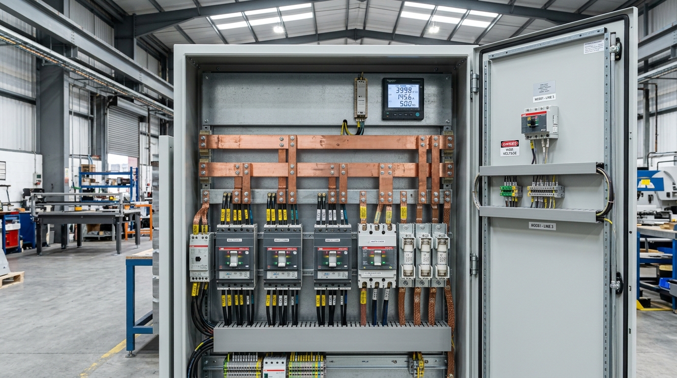
Demystifying the Terminology: North American SCCR vs British BS EN 61439 Metrics
UK machine builders exporting automated equipment to North America or importing machinery from abroad frequently encounter intense confusion regarding short-circuit terminology. While engineers in the United States refer universally to SCCR (Short-Circuit Current Rating) under UL 508A and NEC Article 409, the British and European regulatory framework governed by BS EN 61439-1 structures fault capabilities into three distinct parameters:
| Standard Metric | Governing Standard | Physical Meaning | Typical UK Values |
|---|---|---|---|
| Icw (Short-Time Withstand) | BS EN 61439-1 / IEC 61439-1 | RMS current an assembly withstands for 0.2s, 1.0s, or 3.0s without upstream limitation. | 15 kA, 25 kA, 35 kA, 50 kA (1s) |
| Icc (Conditional Short-Circuit) | BS EN 61439-1 / BS 7671 | Prospective fault current survived when protected by a specific coordinated breaker/fuse. | 35 kA, 50 kA, 65 kA, 100 kA |
| Ipk (Peak Withstand Current) | BS EN 61439-1 | Instantaneous maximum peak current value, defining maximum electrodynamic mechanical force. | 30 kA up to 105 kA peak |
| SCCR (Short-Circuit Current Rating) | UL 508A / NEC Article 409 | Composite assembly rating based on the weakest power component in the panel. | 5 kA (default), 25 kA, 65 kA |
In a UK manufacturing installation under BS 7671 (IET Wiring Regulations 18th Edition), the electrical contractor or consultant must calculate the Prospective Fault Current (Icp) at the panel incoming terminals. The control panel must possess a rated short-circuit withstand (either unconditioned Icw or conditional Icc) equal to or exceeding this site prospective value.
Calculating Prospective Fault Current (Icp) at the Incoming Terminals
Before sizing internal busbars or selecting switchgear, the design engineer must determine the maximum fault current that the distribution network can supply into the panel. Fault level is governed by the upstream supply transformer impedance and cable run characteristics.
Transformer Short-Circuit Contribution Formula
For an industrial facility supplied by a dedicated three-phase distribution transformer, the prospective symmetrical fault current directly at the transformer low-voltage secondary terminals is calculated by:
Where:
- I_sc(trans) = Symmetrical prospective short-circuit fault current (Amperes).
- S_trans = Transformer apparent power rating (kVA or VA).
- V_line = Nominal line-to-line secondary voltage (typically 400V or 415V in the UK).
- z_% = Transformer percentage impedance voltage (typically 4.75% to 5.5% for standard UK distribution transformers).
Consider a common UK manufacturing sub-station equipped with a 1,000 kVA (1.0 MVA) 11kV/400V transformer with an impedance of z_% = 5.0%:
I_sc(trans) = 1,000,000 / (√3 × 400 × 0.05) = 1,000,000 / (1.732 × 400 × 0.05) = 28,867 A ≈ 28.9 kA RMS.
Directly at the transformer secondary terminals, the prospective fault current is 28.9 kA. Any main distribution board or MCC installed adjacent to this transformer must possess a verified short-circuit rating of at least 35 kA to ensure adequate safety margin.
As power cables extend across the factory floor to distant machine control panels, cable impedance (resistance and reactance) attenuates the fault level. For a remote panel located 60 metres away fed by 95 mm² copper SWA cable, the fault level may drop from 28.9 kA down to 14.2 kA. However, our panel engineers always verify the worst-case scenario: a bolted three-phase fault directly on the incoming panel terminals.
Electrodynamic Forces Between Copper Busbars: Sizing Mechanical Bracing
During normal operating conditions, a 250A control panel generates negligible magnetic interaction between its copper busbars. However, during a 35 kA prospective fault, massive electromagnetic fields surround each phase conductor, causing violent physical attraction and repulsion forces.
The Peak Current (Ipk) Factor
A short-circuit waveform is asymmetrical during the first few cycles due to the system X/R (reactance to resistance) ratio. The peak instantaneous current (Ipk) that generates maximum physical stress is related to the symmetrical RMS current (Icw or Icp) by the factor n specified in BS EN 61439-1 Table 7:
For a 50 kA RMS fault level, the peak current reaches Ipk = 50 kA × 2.1 = 105 kA peak!
Calculating Electrodynamic Force (Biot-Savart Law)
Under BS EN 61439-1 Annex P, the mechanical force exerted between two parallel busbar conductors carrying peak fault current is given by:
Where:
- F_m = Peak electrodynamic force acting on the busbar support (Newtons).
- I_pk = Peak asymmetrical fault current (Amperes).
- l = Distance between adjacent busbar support insulators (span length in metres).
- d = Centre-to-centre distance between parallel phase busbars (metres).
- k_factor = Conductor shape and orientation coefficient (typically 0.85 to 1.0).
Engineering Insight: The Critical Importance of Support Spacing (l)
Notice that the force acting on the busbar support increases proportionally with the span length (l) and with the square of the peak current (Ipk²). If an inexperienced panel builder spaces busbar supports 600 mm apart instead of the manufacturer-certified 250 mm spacing on a 50 kA system, the force on each insulator increases by 140%, causing the glass-filled polyamide support brackets to shear, creating an instantaneous catastrophic arc blast inside the cabinet.
Thermal Withstand & Protective Conductor Sizing (The Adiabatic Equation)
In addition to violent mechanical shock, short-circuit currents inject extreme thermal energy into conductors before protective devices clear the fault. The temperature of copper busbars and earth conductors must not exceed the thermal degradation threshold of surrounding insulation (e.g., 160°C for PVC, 250°C for XLPE or thermosetting materials).
The Adiabatic Equation under BS 7671 Regulation 543.1.3
To verify that a protective earth (PE) busbar or copper conductor can withstand the prospective fault current without melting or catching fire, our engineers apply the adiabatic equation:
Where:
- S = Minimum nominal cross-sectional area of conductor (mm²).
- I = RMS fault current flowing through the protective device (Amperes).
- t = Operating tripping time of the protective device in seconds (or from let-through energy curves).
- k = Factor taking account of the resistivity, temperature coefficient, and heat capacity of the conductor material (e.g., k = 143 for PVC-sheathed copper, k = 176 for bare copper busbars).
Under BS EN 61439-1 Clause 8.4.3.2.3, the internal protective earth conductor must be sized to handle the maximum let-through energy (I²t) of the incoming protective device. Furthermore, the cross-sectional area of the main internal PE bar must meet Table 4 minimums: equal to 100% of phase conductor area up to 16 mm², 16 mm² for phase conductors between 16 and 35 mm², and at least 50% of the phase conductor area for large busbar feeds exceeding 35 mm².
Eliminating the Component Bottleneck: Cascading & Current-Limiting Devices
The most pervasive engineering defect identified in industrial control panels across UK plants is the Weakest-Link Bottleneck. Inexperienced designers often install a heavy-duty incoming 50 kA breaker, believing the panel is rated for 50 kA.
However, downstream power branch circuits contain diverse components: motor contactors, thermal overload relays, DIN-rail terminal blocks, miniature circuit breakers (MCBs), and power supplies. If a single component in that power path has an individual withstand capability of only 5 kA or 10 kA, the entire panel rating drops to 5 kA unless coordinated protective measures are deployed.
Strategy 1: High-Rupturing Capacity (HRC) Current-Limiting Fuses
By installing ultra-fast current-limiting fuses (such as British Standard BS 88-2 or Class J fuses) upstream of vulnerable branch components, the fuse melts within the first few milliseconds of a fault.
The fuse physically limits both the peak instantaneous current (Ipk) and the thermal let-through energy (I²t) to a fraction of the available system fault level. This enables 10 kA-rated contactors and terminal blocks to operate safely on a 50 kA supply network.
Strategy 2: Manufacturer Cascading Tables (Series Ratings)
Leading switchgear manufacturers (such as Schneider Electric, ABB, and Siemens) publish certified Cascading / Series Rating Tables based on rigorous physical laboratory testing.
When a specific downstream 10 kA miniature circuit breaker (e.g., Schneider iC60N) is paired with a specific upstream 50 kA moulded case circuit breaker (e.g., Compact NSX), the upstream breaker limits energy dynamically, officially elevating the combination breaking capacity to 36 kA or 50 kA under BS EN 60947-2 Annex A.
Engineering Rule: Cascading is strictly valid only when using tested and approved combinations from the same manufacturer. Mixing a Siemens upstream MCCB with an ABB downstream MCB invalidates published cascading tables and voids the conditional short-circuit rating (Icc) of the control panel.
UK Statutory Compliance: BS EN 61439 Design Verification & HSE Enforcement
Under British statutory law, electrical panels cannot be deployed based on assumptions. Under BS EN 61439-1 Clause 10, the panel builder must compile formal evidence demonstrating design verification across twelve technical criteria, including short-circuit withstand strength.
Original vs Assembly Manufacturer Duties
BS EN 61439 distinguishes between the Original Manufacturer (who designs and tests the system rules) and the Assembly Manufacturer (the panel builder who wires the cabinet). MASK Controls engineers utilize verified system enclosures and busbar arrangements (e.g., Rittal RiLine), ensuring full compliance without costly redundant laboratory type-testing.
The Technical Construction File (TCF)
Every custom control panel delivered by MASK Controls includes a verified Technical Construction File containing fault current calculations, component cascading schedules, EPLAN schematics, routine verification test records (insulation and continuity), and signed UKCA / CE Declarations of Conformity.
Explore our full range of certified engineering capabilities in bespoke electrical control panel design, complex PLC programming services, and on-site installation and commissioning across the UK.
Frequently Asked Questions (Short-Circuit & Fault Rating Engineering)
Click any question below to explore technical answers regarding SCCR, busbar design rules, and BS EN 61439-1 verification.
Q1:What is the key difference between North American SCCR and British BS EN 61439 short-circuit ratings?
Q2:Why does the lowest-rated power component dictate the entire control panel fault rating?
Q3:When is short-circuit design verification by calculation permitted under BS EN 61439-1?
Q4:How do current-limiting fuses prevent mechanical busbar damage during a bolted fault?
Q5:Who bears legal responsibility for fault level verification under UK statutory law?
Eliminate Short-Circuit & Arc Flash Compliance Risk with MASK Controls
Whether designing brand-new 50 kA motor control centres, retrofitting high-fault factory distribution boards, or verifying BS EN 61439 short-circuit compliance for UK machinery, MASK Control Systems delivers turnkey, fully documented EC&I engineering.
Need an SCCR or Fault Level Verification Audit?
Speak directly with our senior electrical systems engineers in Devon. We design, calculate, build, and certify robust industrial control panels for UK manufacturers and OEM machine builders.