
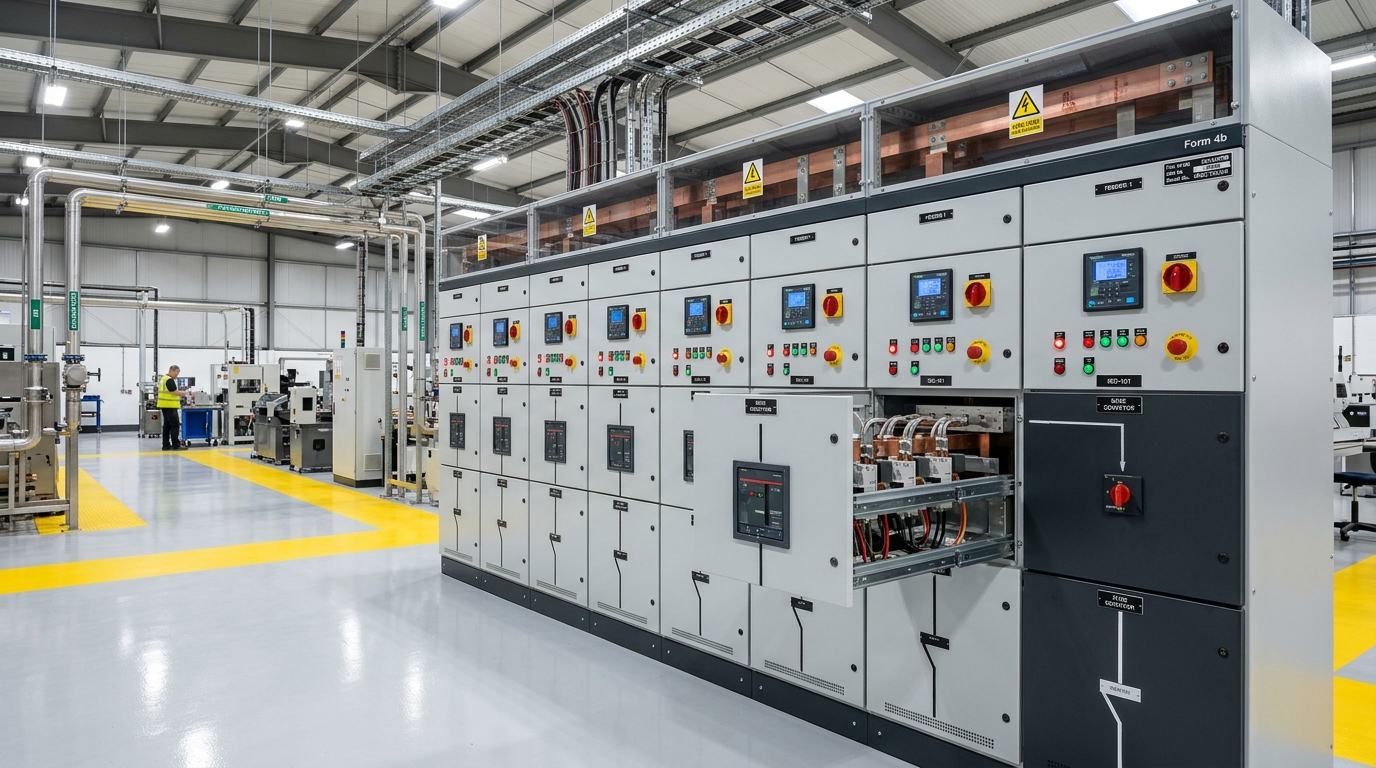
The Core Objectives of Internal Enclosure Separation (BS EN 61439-2)
Under British and European electrical assembly standards, low-voltage switchboards and Motor Control Centres (MCCs) are not mere sheet-metal boxes housing components. They are engineered life-safety barriers. In accordance with BS EN 61439-2 Clause 8.101, internal separation is designed to fulfill three primary operational goals:
- Protection Against Direct Contact (Personnel Safety): Ensuring that maintenance technicians are protected against accidental contact with live adjacent parts (achieving at least IPXXB or IP2X finger-proof protection) when accessing an individual functional unit or cable compartment.
- Limitation of Fault Propagation (Arc Flash Containment): Physically confining internal electrical faults, ionizing gases, and copper plasma caused by a short circuit in one functional unit, preventing the flashover from migrating to adjacent starters or destroying the main incoming busbars.
- Operational Continuity (Continuous Process Uptime): Allowing routine maintenance, fuse replacement, thermal overload resets, or new circuit cable termination while the rest of the switchboard remains energized and productive.
Detailed Breakdown of the Four Fundamental Forms (1, 2, 3, and 4)
The standard defines four basic Forms of Separation, with sub-categories 'a' and 'b' governing the critical relationship between functional units and external cable termination points:
| Form Rating | Busbar Segregation | Functional Unit Separation | External Terminal Separation |
|---|---|---|---|
| Form 1 | None | None | None (all components share common volume) |
| Form 2a | Separated from Functional Units | None (units grouped together) | Terminals NOT separated from Busbars |
| Form 2b | Separated from Functional Units | None (units grouped together) | Terminals separated from Busbars |
| Form 3a | Separated from Functional Units | Separated from each other | Terminals NOT separated from Busbars |
| Form 3b | Separated from Functional Units | Separated from each other | Terminals separated from Busbars (shared chamber) |
| Form 4a | Separated from Functional Units | Separated from each other | Terminals inside same compartment as functional unit |
| Form 4b | Separated from Functional Units | Separated from each other | Terminals in dedicated, separate chambers for each unit |
Why Form 2a and Form 3a Are Rarely Used in Modern UK Engineering
Notice that in Form 2a and Form 3a, the external cable terminals are physically exposed to the main busbar chamber. If an electrician connects an outgoing cable while the main busbars are energized, a slipped screwdriver or falling washer can contact the live 400V copper busbar, creating an instantaneous explosive arc flash.
Consequently, UK consulting engineers and panel builders at MASK Controls almost exclusively specify Form 2b for basic commercial installations and Form 4b for industrial manufacturing facilities.
Decoding the British BEAMA Guide: Types 1 Through 7 Explained
While the international standard BS EN 61439-2 defines the conceptual Forms of Separation, the UK electrical industry relies on the definitive guide published by BEAMA (British Electrotechnical and Allied Manufacturers Association).
BEAMA introduces specific Construction Types (Types 1 to 7) to clarify exactly what materials and mechanical arrangements must be used to build Form 2, Form 3, and Form 4 switchboards:
Insulated Busbar Sleeving
Separation is achieved by wrapping busbars in heat-shrink or PVC insulation. Terminals are separated from functional units, but may share a common cable chamber. Economic, but vulnerable to mechanical damage over time.
Metallic Partitions / Shared Cable Way
Rigid sheet-steel partitions separate busbars and functional units. Terminals for all units are housed in a common vertical cable duct, requiring care during live cable pull.
Independent Terminal Chambers
All separation achieved by rigid metallic or non-metallic partitions. Cable terminals for each functional unit reside in their own segregated compartment, allowing individual access.
All-Metallic & Integral Gland Plates
All barriers must be rigid metallic sheet steel. Every functional unit has its own dedicated compartment, its own dedicated terminal chamber, and its own dedicated integral cable gland plate. The highest safety rating achievable in the UK.
UK Water Industry & Critical Infrastructure: WIMES 3.01 and HTM 06-02
Nowhere is the Form of Separation more heavily scrutinized than in UK municipal water utilities and NHS healthcare estates. A loss of electrical power at a major sewage treatment works or hospital operating theater is catastrophic.
WIMES 3.01 Compliance in Water and Wastewater
The Water Industry Mechanical and Electrical Specifications (WIMES 3.01), adopted by Severn Trent, Thames Water, United Utilities, and South West Water, explicitly mandates:
- Motor Control Centres must achieve a minimum of Form 4 Type 6 or Form 4 Type 7 separation.
- Starters exceeding 15 kW must feature withdrawable or demountable chassis drawers with automatic safety shutters covering the busbar stabs when the drawer is withdrawn.
- Each motor starter compartment must be provided with its own individual padlockable door interlocked mechanically with the local circuit isolator.
- Cable termination chambers must permit full cable glanding, termination of steel wire armored (SWA) cables, and torque verification without removing barriers to adjacent circuits.
Similarly, in healthcare infrastructure under HTM 06-02 (Electrical safety code for low voltage systems), main essential distribution switchboards feeding uninterruptible power supplies (UPS) and clinical emergency generators must utilize Form 4b construction to facilitate annual thermographic surveys and maintenance without dropping clinical loads.
The Financial & Spatial Decision: TCO vs Downtime Risk
Specifying the Form of Separation requires careful financial appraisal. Increasing the Form rating impacts three major physical factors:
| Form Level | Relative Hardware Cost | Cabinet Footprint (Linear mm) | Maintenance Downtime Required |
|---|---|---|---|
| Form 1 (Open Chassis) | 100% (Baseline) | 800 mm | 100% Total Panel Shutdown |
| Form 2b (Busbars Segregated) | 125% - 135% | 1,000 mm | Full Functional Unit Shutdown |
| Form 3b (Units Compartmentalized) | 145% - 165% | 1,400 mm | Shared Cable Way Shutdown |
| Form 4b Type 6/7 (Fully Segregated) | 180% - 240% | 2,000 mm to 2,800 mm | Zero Global Shutdown (Live Feeder Work) |
The Total Cost of Ownership (TCO) Calculation
For a continuous UK manufacturing facility (such as a food packaging plant, plastic extrusion line, or chemical batch synthesis suite), an unplanned 4-hour factory shutdown to replace a single tripped 11 kW motor starter costs between £15,000 and £40,000 in lost production and scrapped raw material.
Investing an extra £12,000 upfront into a modular Form 4b MCC suite pays for itself during the very first scheduled maintenance window or unexpected starter failure.
UK Statutory Compliance: Electricity at Work Regulations 1989
In the United Kingdom, electrical safety in the workplace is governed by criminal law through the Electricity at Work Regulations 1989, enforced by the Health and Safety Executive (HSE).
Regulation 4(1): Construction & Maintenance
Mandates that all electrical systems shall at all times be constructed and maintained so as to prevent, so far as is reasonably practicable, danger. Form of separation provides verifiable physical prevention.
Regulation 14: Work on Live Conductors
Explicitly states that no person shall engage in any work on or near a live conductor unless it is unreasonable for it to be dead and suitable precautions (including barriers and screens) are taken.
Every custom low-voltage switchboard and MCC panel delivered by MASK Controls includes comprehensive design verification records under BS EN 61439-2, detailed EPLAN General Arrangement schematics, routine test certificates, and signed UKCA / CE Declarations of Conformity.
Explore our full capabilities in bespoke control panel design and manufacturing, advanced PLC software integration, and on-site installation, FAT, and commissioning.
Frequently Asked Questions (Forms of Separation Engineering)
Click any question below to explore technical answers regarding BS EN 61439-2 forms of separation, BEAMA types, and switchboard maintenance.
Q1:What is the primary difference between Form 2b and Form 4b separation?
Q2:Why do UK water utilities mandate Form 4 Type 6 or Type 7 under WIMES specifications?
Q3:What level of ingress protection is required for internal barriers under BS EN 61439-2?
Q4:How do British BEAMA Types 1 through 7 relate to international IEC Forms of Separation?
Q5:What is the cost difference between building a Form 1 panel versus a Form 4b switchboard?
Eliminate Switchgear Downtime & Arc Flash Risk with MASK Controls
Whether architecting brand-new Form 4b Type 7 Motor Control Centres for a UK water utility, designing compact Form 2b distribution switchboards for manufacturing facilities, or retrofitting aging switchgear suites, MASK Control Systems delivers turnkey, fully documented EC&I engineering.
Need a Form of Separation or Switchgear Consultation?
Speak directly with our senior power distribution and switchgear design engineers in Devon. We design, build, test, and commission compliant assemblies for UK industry.